Friday, March 24, 2017

Latest Saelig Newsletter - Highlights Pico Technology!


The latest Saelig Newsletter focuses on Pico Technology news: their new 4444 4-channel differential scope and novel probes, new helpful tech videos, as well as useful tech tips.

It's here:   http://bit.ly/2mYhPPz


Thursday, March 23, 2017

New Rigol Support Helps


Rigol has published lots and lots of new app notes and videos to describe in detail the use of their products.  77 articles on scopes alone! 58 on spectrum analyzers, 39 on waveform generators.  Quite a gold mine!

https://rigol.desk.com/  features lots of helpful app notes & articles.


Lots of short training videos are: https://www.youtube.com/user/RigolTech/videos


Rigol also refers to other Channels which exhibit Rigol stuff: https://www.youtube.com/user/RigolTech/channels

And they have a new logo:

"Beyond Measure" has gone away and now it's "Innovation or Nothing". 


Monday, March 20, 2017

Using the AMETRIX Model 101 to Investigate Leakage Currents in Clamp Diodes

Clamp diodes are widely used in analog electronic circuits. Like all real-world components, these diodes have some non-ideal characteristics; this paper investigates some of these characteristics for a few diode candidates. The AMETRIX® Instruments’ Model 101 Picoammeter is used for measuring these small currents.
Reverse biased leakage current is a characteristic of concern for a clamp diode. Ideally the leakage would be zero but this is the real world, so what can one live with? In a typical application there might be two clamp diodes, one to +15 V the other to -15 V and a common connection to the signal to be clamped. The leakage current drops as the voltage drops, so if that signal is nearer to +10 V, then the lower clamp diode would have more leakage than the upper one. So in such an application, a diode with both low leakage and a fairly flat leakage vs. voltage would be desirable.


Figure 1 is plotted data of leakage measurements versus reverse voltage. A quiet DC supply was used along with an AMETRIX Instruments’ Model 101 Picoammeter to measure the current (and yes, that is single-digit femptoamps you are seeing).
Comments about reverse leakage:
1.    The SST4391 is rated for 35 V gate-drain and gate-source
2.    The SST4391 costs $0.057 each
3.    The 2n3904 has a Vcb maximum of 60 V
4.    The MMBT3904LT1G is $0.0231 each
5.    The FLLD261 is $0.0275 each
6.    The BAS16 costs $0.0151 each
7.    The BAT54 costs $0.0204 each
8.    The BAS70 costs $0.0323 each
9.    The MMBD4148CC costs $0.0194 each
So even though there is a 3:1 price ratio between the most and least expensive, they are all < 6¢, so cost is probably not a serious part of the decision process.
The forward voltage drop is another diode characteristic to be considered for a voltage clamp. These measurements were made as follows (the data is presented graphically in figure 2):
1.    Forward bias the diode with a quiet DC supply that has fine resolution; in this case an EDC calibrator
2.    With function generator set to pulse, 1 Hz, 1% duty cycle, drive a mercury wetted reed relay. Connect the relay contacts across DUT such that the DUT is shorted for 990 msec and unshorted for 10 msec; this is to minimize self heating effects.
3.    Measure forward voltage with Tektronix MSO4104 scope with Model 100 Series' probes to minimize the low forward current errors. Set the scope’s bandwidth limit to 20 MHz to minimize noise. Use the scope’s vertical channel’s offset mode and 10 mV range, adjusting the offset knob until trace is in center of screen, then document the offset voltage.


In conclusion, some simple measurements can provide much insight into the components that you think might be ideal in a given application; and they might reveal some things that are unexpected.

Friday, March 17, 2017

Why USB RF Signal Generators Should Be in Your Next Project

Low-cost Universal Serial Bus (USB) radio frequency (RF) signal generators have recently
come on the scene in the wireless world. They promise to be game changers for many
reasons. Until these devices came out, a prospective buyer had two choices when it
came to RF signal generation solutions. The buyer could either purchase a $20K+
benchtop box with all the bells and whistles, or they could purchase a $6K narrowband
“synthesizer”, either hard coded to one frequency, or with an RS-232 programming port
to figure out. Both of these solutions would typically take eight weeks to deliver. They
are generally build-to-order components.
USB RF signal generators are actually a hybrid approach to both of those options
mentioned above—they can be much cheaper and deliver in a couple of days.
A great (made in the USA) example is the Windfreak Technologies SynthHD
Dual Channel Microwave Signal Generator
for $1,279. This price is surprisingly cheaper than some RF test cables.
MSG Microwave Signal Generator

SynthHD

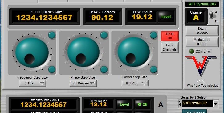
The device has two independent channels that can tune in 0.1 Hz increments from
54 MHz to 13.6 GHz. The SynthHD’s RF power is adjustable in .01 dB increments
from -50 dBm to +22 dBm. It also has many modulation features including FM chirps.
The relative phase between the two channels can be adjusted in .01 degree increments.
It is a hybrid approach because the device can either be controlled
with a PC graphical user interface (GUI) like benchtop test and measurement (T&M)
equipment, or it can be programmed to function as a module inside a communication
system without a PC, like the narrow band synthesizer mentioned above.
The SynthHD signal generator will generate sweeps. The sweeps can be single
channel or dual channel. The device can sweep up or sweep down. It can also ramp
up or down amplitude while sweeping. The sweep can be controlled with an external
trigger to either perform a full sweep per trigger, or perform a single step. In dual
channel mode you can program a constant frequency offset between
the two channels for the sweep.
The SynthHD signal generator will generate hops. The GUI allows the user to program
up to 100 arbitrary points with a frequency and amplitude in dBm. This table is stored
onboard in nonvolatile memory. Like the sweep mode the user can then have an offset
on the other RF channel, hop up the list, hop down the list, and work with the trigger input.
Additionally, the SynthHD signal generator will digitally modulate FM, AM, and pulse.
FM can be a typical sinusoidal signal, or it can also be a chirp. AM can also be the t
ypical sinusoid signal or it can be ramps. The modulations can be combined. Combining
a pulse and a chirp allows the user to set up a frequency modulated continuous wave
(FMCW) radar signal. You can even combine this with the sweep function. As an
electronic warfare example, you could sweep a pulsed waveform across a range
of frequencies. Rates can be very slow, or in the case of FM, up to 5 KHz. Of course,
all of these features can be saved to the device; it will begin sweeping on power up
without a PC connected!
Use the external Trigger connection to perform external modulation such as
FM, AM and Pulse. More details here!!!!

SynthHD and SynthHD Pro Software GUI


microwave-signal-generator-sw1

Thursday, March 16, 2017

Windfreak's SynthNV RF Generator - review by Kenneth Wyatt

http://www.saelig.com/supplier/windfreak/Review--Windfreak-Technologies-SynthNV-RF-generator--Part-1-.pdf

Kenneth Wyatt - November 25, 2013: Every once in a while, I discover a product that is so incredible I wonder why it hasn’t been publicized more widely. This is the case with Windfreak Technologies $599 miniature RF generator, the model “SynthNV” (Figure 1). In case you’re wondering, their company is named after the owner’s sailboat!


Figure 1 - The Windfreak Technologies SynthNV RF generator weighs just a few ounces and easily fits in your hand.

For months, I’ve been seeking a small RF generator that could replace the 40-pound monster I keep under my workbench. What really caught my eye initially was that the generator could AM modulate the RF output - perfect for radiated immunity pre-compliance testing! In addition, it will pulse modulate the output - perfect for testing to the MIL-STD-461 and DO-160 standards. The RF output level is sufficient to drive a near field probe with enough field strength to investigate susceptibilities within a product’s internal circuitry. But wait, there’s more! Here’s rundown of the features of this palm-sized jewel. Some of these additional features will be reviewed in Part 2 of this series. • RF sweep generator (34.4 MHz to 4.4 GHz at up to +19 dBm output) • Network analyzer (34.4 MHz to 4.4 GHz) • VSWR analyzer (using external power coupler) • RF power meter (real time) The generator is USB powered and can run on most Windows operating systems, including Windows 8. It also includes an external power adapter input, so it can be programmed into a given state and then disconnected from the PC and run standalone as a local oscillator or RF generator. There is a port that can source or receive an external 10 MHz clock, as well as an RF input port for measuring power. This port is also used for the network analyzer function.


Figure 2 - The basic user interface for the generator is based on National Instruments Labview.

The well designed user interface (Figure 2) is based on National Instruments Labview and the provided software includes the runtime engine for those who don’t own the full Labview software. It installed and ran just fine on my Macbook Pro with Parallels 9 and Windows 8. There are several tabs along the left half of the panel. These select the major functions of the instrument controller. When in manual mode, the large knob tunes the frequency in preset steps of 1kHz, 10kHz, 100kHz, 1MHz, 10MHz and 100MHz. The user may also enter frequencies directly by typing in the data blocks or by using a keyboard control in place of the large knob. The nominal +19 dBm RF output power is controlled by the rightmost panel. There are two buttons controlling the preset output. The High Power button will switch between the default high power or when pressed decreases the overall power output by about 55 dB (Low Power). A second button turns the RF on/off. The slide control further adjusts the output power by up to 31.5 dB. Note that the power scale is “dB’ and not the actual output power in “dBm”. This can be confusing at first, because the natural inclination is to assume the scale corresponds to the actual power output. This requires some mental calculations (or confirmation measurement) to set the precise output level. I suspect one slick way to confirm the desired power level is to run the output (through attenuators) to the “RFin” port to make that measurement. One improvement might be to redesign the slider to conform to the actual output power level - changing the scale according to the three preset power levels.

In stock at Saelig Co. Inc here!

Wednesday, March 15, 2017

Identify Machine Problems Before They Happen

Effective non-contact torque monitoring can help production quality as well as identify machine problems before they happen.

The importance of torque measurement in manufacturing environments is a new concept to some, but an everyday essential to others. Realizing the enormous cost benefits of measuring torque in rotating systems is sometimes not recognized by those tasked with improving profitability. The challenge is to be able to monitor and measure torque as accurately, unobtrusively, and economically as possible. For continuous-manufacturing processes where machines are driven by rotating shafts, machinery failure and subsequent downtime must be avoided in order to maintain profitability as well as consistency of output. The effective use of precision non-contact torque monitoring instrumentation can preemptively identify problems that might affect machinery reliability—extremely important for situations where a single machine failure can lead to costly production losses.

Read more here:  http://www.saelig.com/supplier/saelig/MTM-10-2015-Saelig_1.pdf


Tuesday, March 14, 2017

What are the key benefits of using ABI's PCB testers?

ABI customers save money repairing complex others said were impossible to .

Customers around the world are enjoying reduced time to fix boards, which produces savings in operating costs and equipment downtime.

http://www.saelig.com/category/MFR00134.htm


Monday, March 13, 2017

New Pico 4-ch Channel High Resolution Oscilloscope With Differential Inputs


Today we've introduced the PicoScope 4444 High-resolution Differential Oscilloscope which features four true differential input channels and a range of accessories for measurements from millivolt to 1000 V CAT III applications. It has been designed specifically for making accurate voltage waveform measurements on circuits that are not ground-referenced, avoiding the dangers of equipment damage due to short circuits.
The PicoScope 4444 can facilitate differential voltage measurements in the presence of common-mode signals, with 14-bit resolution and 20MHz bandwidth on all four differential channels and 256MSa waveform capture memory. It is ideal for the precise analysis of complex waveforms ranging from biomedical sensors to current probes and 1000 V CAT III power distribution circuits. The PicoScope 4444 offers a choice of complementary 1:1 low-voltage and 25:1 1000V CAT III probes to address these and other situations. The oscilloscope has an intelligent probe interface that can provide power for a wide range of PicoConnect voltage probes, current probes such as Hall effect DC/AC, and Rogowski coil type active current probes. The scope automatically detects when a compatible probe is connected and sets the corresponding units and vertical settings in the supplied PicoScope 6 software.

The USB-powered PicoScope 4444 is available in two kits that include key accessories:

·         PicoScope 4444 Standard Differential Oscilloscope Kit, consisting of a PicoScope 4444, three differential 1:1 probes and one TA271 BNC single input adaptor.

·         PicoScope 4444 1000 V CAT III Differential Oscilloscope Kit, consisting of a PicoScope 4444, three 1000 V CAT III 25:1 differential probes and one BNC input adaptor.

Scientists and electronics engineers frequently need to make low-voltage measurements in the presence of high common-mode noise or varying offset voltages. Ground-referenced oscilloscopes require the use of two input channels and an A–B math function to observe the differential signal of interest. But, in addition to requiring two input channels, most scopes don’t have a high enough common-mode rejection ratio (CMRR), nor the resolution to make measurements with sufficient precision.  Engineers working on polyphase power distribution systems need to measure phase-to-phase AC voltages, rather than phase to ground. A ground-referenced scope can’t be used as it will cause a short circuit. External differential probes are a solution but they are quite expensive and cumbersome, with each probe requiring its own power supply. The PicoScope 4444 provides the solutions for each of these situations, but it can also be used as a general purpose scope with all the useful features that PicoScope software provides - such as serial bus decoding, mask and limit testing, math channels and automatic measurements.
Made by Pico Technology, Europe’s award-winning oscilloscope adapter manufacturer, PicoScope 4444 High-resolution Differential Oscilloscopes are available now from Saelig Company, Inc.  For detailed specifications, free technical assistance, or additional information, please contact Saelig 888-7SAELIG, via email: info@saelig.com, or visit www.saelig.com

Friday, March 10, 2017

What the English Say versus What the English Mean

As a Brit myself, this is accurate: "What the English Say versus What the English Mean"


German elevator manufacturing company invests in new test technology


Customer: German elevator company with manufacturing facility in Brazil


Problem: New electronic cards are assembled by third party companies and shipped to elevator manufacturer in the south of Brazil. The end of production test carried out by the automatic test equipment (ATE) is slow and gives little information about the fault location if PCB fails the test. Operators have to follow traditional work instructions and instrumentation (PSU, scopes, multimeter) which is time-consuming and ineffective. The test area became a bottleneck and PCBs are being scrapped when faults are not found quickly. Similar problems being faced by manufacturer's offices in Chile, Argentina and Mexico which rely on R&D team in Brazil for advice.

 Solution: ABI distributor showed how the existing process could be replaced by SYSTEM 8 Modules and TestFlow.  ABI introduced the following scenario to be implemented at the third party PCB manufacturer (CEM):

  •  ABI hardware (BoardMaster) could be connected to an interface card (designed by mfr) populated with relays that would switch on/off according to logic patters output by the ATM module 
  • The interface card would be linked to other modules (eg. AMS, MIS 4, VPS) and a test fixture (bed of nails) developed for most critical PCB designs 
  • A sequence including Power Off/ Power On tests was set up using TestFlow Manager 
  • A detailed report would be generated including any fault information. The report would be submitted to the R&D for analysis and operators could run a component level test to troubleshoot most expensive PCBs 
  • This setup could also be put in place by other elevator plants in Latin America

 Outcome: A group of 5 test engineers evaluated the proposal from ABI and presented the project to the company's directors. An initial investment was approved and the order has been placed with ABI.

 Products purchased: 2x 7 Bay BoardMaster with ATM, 2x AMSAICTMIS 4 and VPS plus accessories.

Thursday, March 9, 2017

GW Instek's Versatile PEL-3031E 60A Electronic Load

GW Instek's new PEL-3000E series programmable single-channel electronic load. In the series, PEL-3031E provides 300W (1V~150V/60A) and PEL-3032E provides 300W(2.5V~500V/15A) current sink capability. Inherited from the PEL-3000 series, PEL-3000E has an easy-to-read LCD panel and user-friendly interface. This model features high speed and accurate measurement capability for electronic component, battery, portable charger and power products that require low to medium power consumption.
The PEL-3000E series is designed for current sink operation starting from 60mA and aims at measurement applications, including charger, adapter, various power supply equipment, and portable charger.
The PEL-3000E has seven operating modes. Among them, four basic operating modes are constant current, constant voltage, constant resistance, and constant power. Three other combined operating modes are constant current + constant voltage, constant resistance + constant voltage, constant power + constant voltage. Users can select operating modes based upon products' test requirements. For C.C. mode, electronic load will sink a constant current according to the set current value; for C.V. mode, electronic load will attempt to sink sufficient current to control the source voltage to the programmed value; for C.R. mode, electronic load will sink a current linearly proportional to input voltage according to the set resistance value; for C.P. mode, electronic load will initiate load power sinking operation (load voltage x load current)in accordance with the programmed power setting.

To meet the requirements of different test conditions, the Static function is to sink a constant current; the Dynamic function is to periodically switch between two sink conditions, and the Sequence function is to provide tests for more than two sink conditions. The sequence function can be divided into Normal Sequence and Fast Sequence. Normal Sequence is the most flexible mean of generating complex sequences that can facilitate users to establish a set of changing current sink conditions based upon different sinking conditions (CC, CR, CV or CP mode) and time(adjustable range: 1ms to 999h 59min 59s). Fast sequence allows time resolution of 25us to be set for the smallest step. Setting parameters for multiple steps can simulate consecutive current changes of various real load conditions. For instance, while using an electronic load to test a power-driven tool's power supply, we can first obtain waveforms by an oscilloscope and a current probe from the tool, and subsequently, use the obtained waveforms to edit simulated current waveforms, via electronic load's sequence function, to test the power-driven tool and to analyze its operational status. The Soft Start function allows users to determine the rise time of current sink that is to decide the required time to reach electronic load's set current, resistance or power value. Setting a proper rise time for Soft Start is effective to counter output voltage fluctuation caused by DUT's (power supply) transient output current. It is worth noting, General DC loads do not have the soft start function.
When conducting high speed current sink operation, the inductance effect on the cable connecting electronic load and DUT will lead to transient voltage drop on electronic load's input terminal, therefore, that will result in Voltage Non-monotonic increase. PEL-3000E's soft start function not only allows output voltage to be Monotonic increase, but also prevents inrush current and surge voltage from happening on DUT. For instance, tests using a power supply, LED and a DC load (activate the soft start function) can prevent inrush current and surge voltage from causing damages on LED.
The built-in BATT Test Automation of PEL-3000E provides battery discharge applications with more flexible discharge stop setting as well as rise and fall Slew Rate for discharge current settings. OCP, OPP test Automation for DUT (ex. Power Supply), provide users with high resolution measurement values to verify DUT's activation point. Provide users with measurement results so as to help them determine whether DUT's actual over protection activation point meets the regulations. Other than that, PEL-3000E provides users with analog control terminal to control PEL-3000E from external voltage, external resistance and switch. Analog control terminal can also monitor electronic load's status and display protective alarms.

Wednesday, March 8, 2017

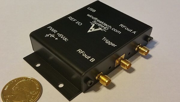
GW Instek’s New MFG-2000 Multi-channel RF Function Generators


Multi-channel signal outputs satisfy diversified signal requirements

The new MFG-2000 Series Multi-channel Function Generators from GWInstek includes both the MFG-21XX entry-level models and the MFG-22XX advanced models with up to five functional channels.  Channels 1 and 2 provide high-performance arbitrary function generators up to 60MHz; Channel 3 - the RF signal generator channel, with output up to 320MHz, is a full function signal source; identical to CH1/CH2, it can output sine, square, ramp, pulse, noise, etc. as well as various RF modulation schemes such as AM/FM/PM/FSK/PWM, Sweep, Burst, Trigger.  Also included in each model is a 25MHz pulse generator channel with adjustable pulse width, duty cycle, rising and falling edge time.  Some models also feature a low-distortion 100kHz Power Amplifier channel - ideal for audio signals. A 150MHz Frequency Counter channel  is available on some models too.  All five different functionality channels operate separately and have grounds that are isolated from the instrument chassis, making these instruments ideal for floating circuit tests. A built-in DC bias voltage can also be applied to the various waveforms.  The front panel, with its clear 4.3” TFT color display, allows arbitrary waveforms to be selected, edited, stored, recalled, output, and triggered from a choice of 66 built-in waveforms.

The AFG channel of the MFG-2000 series outputs sine, square, and triangle, etc. True point-by-point output 14-bit arbitrary waveforms are created with a 200MHz sample rate, 100MHz waveform repetition rate, and 16kpts memory depth. The synchronized MFG-2200 dual-channel models provide correlated functions, including synchronization, delay, sum, and coupling.
The MFG-2000 series function generator can be used with the supplied Arbitrary Waveform Editing Software to allow users to easily and quickly edit arbitrary waveforms. Its Direct Waveform Reconstruction feature allows users to retrieve waveforms from the GDS series of GWInstek digital oscilloscopes and upload them to the arbitrary generator to achieve faithful captured waveform reproduction.  With the multi-functionality channels, the MFG-2000 series provides special dual channel waveforms for specific industrial needs, such as IQ modulation signals, low-frequency vibration simulation, automotive sensors, AM/FM broadcast signals, PWM motor or fan control signals, pulse synchronized signals, pulse noise, audio signal simulation, etc.

The MFG-2000 series supports various frequency and amplitude sweeps such as linear/logarithmic, one-way (saw tooth)/two-way (triangle), and others for carrying out frequency response tests on circuits and components. The tracking function of the MFG-2200 series can produce 180 degree phase offset differential signals with same frequency and amplitude. The phase function allows users to freely set phase parameters for both channels on sine wave, cosine wave, and square wave signals. The sum modulation function can combine two signals into one and output this signal via one channel, such as adding a sine waveform and a noise signal to perform speaker distortion tests.
The MFG-2000 series of function generators are ideal for a wide range of applications, including scientific research, education, R&D, production, and quality control, etc.  Made by the Taiwanese test and measurement specialists GWInstek, MFG-2000 generators are available here from Saelig Company Inc. 
Tuesday, March 7, 2017

Saelig Introduces ThunderSync16 Universal USB Thunderbolt 16 Port Hub

The Cambrionix ThunderSync16, which provides 16 x USB2.0 ports and a Thunderbolt host connection, capable of transfer speeds of up to 20Gbits/s to allow large data transfer in the shortest possible time.  For data syncing requirements, the data transfer speed offered by Thunderbolt delivers a greatly increased data transfer rate between a host Thunderbolt connection and 16 attached devices than a USB2.0 connection.

The ThunderSync 16 speeds up situations needing large data transfer - such as video file uploading or operating system updates - when the data is required to be loaded in the fastest possible time. It is a finished solution in a compact, durable, easy-to-use form factor. 
The ThunderSync 16 supports universal, intelligent charging of USB ports at up to 2.4A simultaneously, and is not limited in the number of USB devices that can be attached due to each port having its own USB host controller.  For more than 16 ports, the ThunderSync16 can simply be daisy-chained via the dual Thunderbolt ports.  To give an idea of speed: a recent lab test scenario achieved a 10x reduction in transfer time; a 5GB file transfer to 16 devices took only 4 minutes compared to more than 40 minutes for a typical USB transfer scenario.  Thunderbolt transfer speeds are around 20Gb/s, while USB2.0 only offers 480Mb/s per port.
The ThunderSync 16 allows the charging of multiple device types simultaneously, irrespective of manufacturer, such as tablets, ChromeBooks, mobile phones, MP3 players, e-readers, 3D Glasses, etc.  Whatever device is connected, the pre-programmed Very Intelligent Charging protocol insures the correct charging profile is used for the specific product, maintaining battery performance and extending battery life without risking damage to expensive technology products. The ThunderSync 16 is designed to operate with the complementary Cambrionix LiveView app which provides the user with complete control and monitoring.  This supplied software demonstrates the unique benefits of Cambrionix patented technology, and displays the charging status in detail.  It shows each port, if a device is attached, and how much energy it is using.  Individual ports can be configured for either Sync or Charge mode, or turned off.  An API is also provided for software automation scripting, essential for software QA and mobile phone remarketing companies.
The ThunderSync 16  is perfect for use by manufacturers, defense, security, software QA, and wearable camera companies who perform large scale charging and data transfer. It is powered by an internal universal power supply, and is Intel Certified, CE Marked, UL Listed and EMC FCC tested.

Monday, March 6, 2017

How can virtual instruments help me get my testing work done faster?

See   http://bit.ly/2megvej


Key advantages of using virtual USB driven instrumentation combined with an easy to use software platform:
1. It allows you to standardize test procedures whilst minimizing human mistakes. Manual, repetitive tests are difficult to carry out without mistakes being picked up along the line. Having the ability to set and recall instruments as well as targets and tolerances will eliminate the risk of human error. Also, your measurements will be always consistent across the team. Your staff meetings will be less about stressing the need of adopting a uniform, standard approach to testing and more about praising performance and productivity.
 2. It saves you time. In many occasions the operator will need to take repetitive measurements across a wide range of values. Virtual instrumentation along with ABI's TestFlow (link for video) gives you the opportunity to automate the process and eliminate the need of having an operator spending time "triple" checking instructions before configuring the instrument to take the measurement thus avoid getting electrocuted. (pun intended)
 3. Creation of test rigs is made easy. Instruments can be customized and combined to solve common issues. Without having to know programming languages, the most used functionalities of the default instruments already available in the software can be merged into new, personalized designs, built for specific purposes. These designs can be recalled as often as required and easily shared with other members of the team in the building or on the other side of the world.
4. Results are logged in customized reports. At the end of each test, software generated reports will be available in HTML, CSV or Database formats. These will include a full result log along with product code, batch number and operator ID. Other options include time taken to complete each step as well as the full cycle.
5. Intelligent testing doesn't need to be complicated. Combine multiple instruments to perform more complex testing actions using basic programming skills. For example, signals can be output into the circuit using an AWG and, upon sensing the correct voltage value on the test point, the DMM will trigger the DSO to start acquiring the waveform at a different test point. All this can be transparent to the user who will just need to follow the instructions on the PC monitor and attach the colour coded probes to the corresponding test points and press Start. PASS/FAIL results will be displayed depending on the results found and whether or not they match the pre-set tolerances.
If you see value in the benefits above you should be seriously considering looking deeper into the ABI's SYSTEM 8 MIS4 module. With a price that works out at less than the price of the individual instruments the module brings under its case, the MIS 4 is supplied and supported in 60 countries by ABI global distributors. The SYSTEM 8 Ultimate Software along with with the popular TestFlow Manager is included in the package and it's free of any maintenance/plug-ins/service charges. You get software updates straight from the manufacturer's website without paying anything extra for it.
Check out a case study showing how a leading technology manufacturer achieved 50% reduction in their end of line measurement process with the MIS4 + TestFlow.

Friday, March 3, 2017

CleverScope Frequency Response Analyzer & Impedance Measurement

If you are designing or verifying feedback systems such as power supplies, audio power amplifiers, servo amplifiers and physical positioning systems it is very helpful to measure the Gain/Phase response of the feedback loop. You can use the Phase Margin as a measure of stability. Values of 50-60 degrees represent the optimal response to a step change in load or signal, without oscillation or sluggishness.


The Cleverscope Frequency Response Analyzer (FRA) uses the CS701 isolated Sine Wave Generator to stimulate the feedback loop at the output of the power supply or amplifier - just where a load would be applied. You don't need an injection transformer as more traditional approaches use, which means you get operation from DC to 65 MHz, no distortion from the transformer, and lower cost.

Using a CS328A-FRA you can plot and visualize stability and transient response on a live system. The 300 V RMS isolated CS701 can be used on mains powered systems safely, while the +/- 24V DC offset capability of the input to the CS328A-FRA means you can measure the response down to DC in power supplies of up to +/-24V. For higher voltage power supplies, use AC coupling. In addition you can use the CS328A-FRA to measure the Impedance and Phase of feedback networks, transformers, PCB power planes, capacitors, resistors and inductors.

The FRA Control Panel makes is easy to set up everything in one place - you don't need to know how to use the rest of the Cleverscope system - and you can also measure Capacitance, Inductance, Effective Series Resistance, Dissapation Factor and the Quality Factor of components. Using the FRA control panel you can fully evaluate a transformers transfer response, the primary and secondary inductances, the leakage inductance and interwinding capacitance, all over frequency. Using DC offset you can check saturation and DC sensitivity. You don't need to buy an expensive Network Analyser because the Cleverscope FRA does all this for you over a 0-65Mhz frequency range!

Why not check out our Cleverscope FRA white papers - this one on Power Supply response, and this video on Impedance Measurement.

Also check out these videos:

http://www.youtube.com/watch?v=T6dew2No85g&feature=player_embedded

http://www.youtube.com/watch?feature=player_embedded&v=blZ7qCAPwHY