Friday, September 29, 2017

USB DrDAQ Data Logger Intros PC-based data logging.

Whether you’re a teacher, student, hobbyist or professional the USB DrDAQ Data Logger gives you an inexpensive entry into the world of PC-based data logging.


The USB DrDAQ Data Logger really is all that you need with these features:
  • Built-in sensors for light, sound and temperature
  • 4 digital inputs and outputs
  • 3 sockets for external sensors
  • Ultra-high impedance input for pH or Redox measurements
  • 100 kHz, 8-bit oscilloscope with a ±10 V  range
  • Signal generator with AWG for creating your own waveforms
  • Captures fast signals
  • USB connected and powered
  • Use up to 20 USB DrDAQs on a single PC
  • Supplied complete with PicoLog, PicoScope and an SDK

Sensors

Thanks to the built-in sensors for light, sound and temperature you can start using your USB DrDAQ Data Logger straight out of the box. (Doctor DAQ has also included an RGB LED that you can program to show any 1 of 16.7 million colors.)  When you want to do more with your DrDAQ you can, thanks to the external sensor sockets. Simply buy an external sensor and your DrDAQ can measure humidity, oxygen levels, external temperatures and more. We provide you with all you need to know to connect external sensors to your DrDAQ so you can even design and use your own sensors.

Digital I/Os

Your USB DrDAQ also includes 4 digital input/outputs. In input mode these give you even more monitoring options. When used as outputs they enable you to use your DrDAQ to control external devices. 2 of the digital I/Os include a pulse-counting function when used as inputs, and a pulse-width modulation (PWM) output capability.

More than just a data logger

Thanks to the power of your DrDAQ you can also use it as an oscilloscope or spectrum analyzer. Just run the supplied PicoScope software and your DrDAQ becomes a single-channel scope with a 100 kHz  bandwidth, 8-bit resolution and the ability to measure voltages of up to ±10 volts.
But that’s not all. Your DrDAQ also includes a signal generator. The signal generator output not only includes a standard function generator, but also an arbitrary waveform generator (AWG) too. Using the AWG function you can create your own waveforms.

All the software you want — and it’s free

The PicoScope oscilloscope software uses the power of your PC or laptop to deliver high performance, and has an easy-to-use Windows interface. All of its advanced features, such as spectrum analysis, automatic measurements and statistics, are included in the price of your USB DrDAQ.
PicoLog is a powerful yet flexible data acquisition program designed for collecting, analysing and displaying data over long or short periods of time. Data can be viewed both during and after collection in spreadsheet or graphical format. The data can also be easily exported to other applications.
If you want to write your own software or use the DrDAQ with third party software we provide a free software development kit (SDK). The SDK includes drivers for Windows XP (SP2 or later), Vista and Windows 7 (32- and 64-bit), and programming examples for C, C++, LabVIEW and Excel.

Hobbyist, student or professional — DrDAQ is all you need

The USB DrDAQ Data Logger has something for everyone: whether you’re a teacher looking for a fun way to perform data logging experiments in the classroom, a student wanting an inexpensive introduction to data logging and oscilloscopes, a computer programmer who wants to use C++ to monitor and control inputs and outputs of real-world devices, an hobbyist who wants to monitor and control their environment, or a professional wanting to measure pH under laboratory conditions — DrDAQ is all you need.

More here:  https://www.saelig.com/product/PSPCEL007.htm


Thursday, September 28, 2017

5 Design Tips to help prevent RF interference in PCB designs.

The www.ema-eda.com blog recently featured an interesting PCB layout article:

With almost everything we own is sending and receiving wireless signals, RF interference is a growing concern. Even if you aren’t transmitting, you may have RF sensitive circuits you need to protect—almost every wire becomes an antenna or receiver and the signals they can receive or transmit can degrade overall performance. This is true for all products, no matter how small or minor they might be.  It is critical to have a good understanding of how design parameters can affect RF interference levels.


Shielding (a “moat”) is important to incorporate on critical sections of the board to prevent interference, or to prevent interference from other portions of the board, affecting sensitive circuits. The moat is that area in the PCB that keeps RF on one side and other signals on their side. Many RF vendors define signal quality by signal-to-noise ratio (SNR), the difference between the received signal and the background noise level. The “moat” must encompass all RF parts/circuitry and is the land pattern for the fence or metal can.

The ground connection needs to take the shortest path to ground so it has the least likelihood to catch anything on fire. This is the same with PCB Design. Ground location is the first line of defense when it comes combating RF interference.  Shielding on the layer RF ground plane should be placed directly below component layer. This paired with vias will allow the noises picked up to go straight to the RF ground plane. This will help to minimize noise, since we cannot truly eliminate it. 

Read on here:  http://bit.ly/2k4asK0

Wednesday, September 27, 2017

All-in-one Testing Tool Provides Many benchtop Instruments In One Box

The Multiple Instrument Station MIS4, is an all-in-one testing tool that provides all commonly required test instruments in one compact programmable hardware module, mounted in a compact case or installed in a PC drive bay.  Controlled by ABI’s sophisticated SYSTEM 8 Ultimate PC software with a simple yet programmable operator interface, the MIS4 combines eight laboratory instruments: a 3-channel 350MHz digital storage oscilloscope with sophisticated triggering options and automatic measurements; a 1.1GHz frequency counter and three 350MHz counters; a 14-bit dual-channel 25MHz arbitrary waveform function generator; a fully floating ammeter; a fully floating voltmeter; a fully floating ohmmeter; multi-rail 4-channel power supplies; and 8 programmable I/O channels to cover almost any test and measurement need. 
The MIS4 comes complete with the Windows-based TestFlow Manager, a step by step sequence of tests that guides operators during fault-finding or test procedure processes. Along with the specific instruments required for a test, additional instructions, photos, PDFs, videos and other documents can be included in a test sequence design to make complex test procedures understandable and repeatable. Automatic instrument setup speeds up test operations and set-by-step test sequences enables rapid operator training.  TestFlow Manager sequential testing reduces the risk of inaccurate measurements and automatically saves all test parameters for a final customized test report. It removes subjective operator data interpretation by using automatic results comparison. This frees an engineer’s time by allowing semi-skilled operators to run test procedures repeatably and accurately. This provides a much faster and more economical testing solution than using traditional oscilloscope, metering and other bench test methods, and can quickly produce the required Pass/Fail or other test and debug results.
 
Solving troublesome test situations where it takes a long time to set up a test procedure, or where instrument settings become inadvertently changed, MIS4 provides a simple combination of appropriate instruments in one compact, space-saving box.  Basic control via its versatile user interface allows problem solving by staff with a range of skill levels. Custom instruments can be created for individual operators to provide an ideal platform for computer-based training or specific or repetitive test routines. The sophisticated TestFlow Manager can remember unlimited test configurations, controlled by access levels with password protection, so that each operator can save instrument settings and recall them in seconds.
 
Applications include:
  • production test, education
  • automotive, manufacturing
  • oil & gas, telecommunications
  • maintenance
  • PCB testing and troubleshooting
  • power-on/power-off testing
  • QA reporting
  • automated test sequences

Monday, September 25, 2017

Use Your Strengths, Have An impact, Make a Living, & Bring Joy!


With no direct English translation, Ikigai is a Japanese term that embodies the idea of happiness in living. Yukari Mitsuhashi explains here: https://lnkd.in/dFub88j


For Japanese workers in big cities, a typical work day begins with a state called sushi-zume, a term which likens commuters squeezed into a crowded train car to tightly packed grains of rice in sushi.

Essentially, ikigai is the reason why you get up in the morning

The stress doesn’t stop there. The country’s notorious work culture ensures most people put in long hours at the office, governed by strict hierarchical rules. Overwork is not uncommon and the last trains home on weekdays around midnight are filled with people in suits. How do they manage?

The secret may have to do with what Japanese call ikigai. There is no direct English translation, but it’s a term that embodies the idea of happiness in living. Essentially, ikigai is the reason why you get up in the morning.

Read on:  https://lnkd.in/dFub88j


Friday, September 22, 2017

How quickly can you recover a capital investment? 

We have just supplied ABI BoardMaster PCB equipment to San Francisco Municipal Transportation Agency (SFMTA) for keeping their new Siemens rolling stock running.  Our U.S based training instructor spent a solid 10 days teaching a team of technicians there to use the ABI equipment. 


Feedback from the team today on how the training went was very interesting! The SFMTA technicians were amazed to see how the ABI's test and repair equipment is to use. Because our training is 80% "hands-on" practical, two of the SFMTA's high value faulty electronic PCBs were fully repaired by their newly-experienced tech team during the hands-on training session that ended yesterday.

That's just an example on how fast ABI customers can recover their investment! Let us help you start saving time and money today. #Repairdontwaste

Call Saelig today at 585-385-1768 or see ABI products here:  http://www.saelig.com/category/MFR00134.htm

Thursday, September 21, 2017

You've Not Seen a 100MHz Mixed Signal Oscilloscope Like This Before!


ABI CircuitMaster 4000M Precision Active Oscilloscope

ABI CircuitMaster 4000M Precision Active Oscilloscope
The CircuitMaster 4000M Precision Active Oscilloscope is unlike any other 100MHz mixed-signal oscilloscope as it provides some innovative test and measurement functions that enable engineers and technicians to perform several new types of circuit analysis.
The CircuitMaster 4000M is designed for safe probing of closely spaced components by adding precision DC measurement, signal storage and analysis functions to a traditional oscilloscope design. Indeed, a built in accurate voltmeter (24 bit) removes the need for multiple instruments, thus making the CircuitMaster a complete test and measurement station. In addition, the Active mode allows signals (AC and DC) to be injected into the board when required, allowing circuit conditions such as drive strength and source impedance to be checked – which is not possible with traditional oscilloscopes. In AC Active mode, the unit behaves much like a function generator. The CircuitMaster even has a built-in LogicView 4 channel analyser for logic signal display along with the 2 analogue inputs. FirmFlex and VI Curve functions provide impedance signature analysis on powered and un-powered boards.

Features:

  • 100MHz digital storage oscilloscope
  • 0.1% 24 bit digital DC voltmeter
  • Active mode - DC and AC function generator
  • FirmFlex node impedance analyzer
  • Multi-range 2 channel VI tester with pulse outputs
  • 2 analogue channels + external trigger
  • Multiway 40 channel signal multiplexer
  • Automatic and cursor waveform measurements
  • WaveStack signal acquisition memory
  • Stored and live tolerance mask waveform comparison
  • LogicView 4 channel variable threshold logic analyzer
  • USB interface for updates, settings and waveform storage

  • Application details here:

    http://www.saelig.com/supplier/abi/circuit-master-4000.pdf

    Wednesday, September 20, 2017

    LoRaWAN Covers the World!

    Latest coverage map showing the global reach of network.


    Our LoRaWAN Field Test Device from European supplier Adeunis lets you do network validation prior to your solution deployment:

    http://www.saelig.com/MFR00007/lorawan-915.htm


    The LoRaWAN Field Test Device by ADEUNIS RF is a ready-to-use system which provides connection to any operated network using the LoRaWAN V1.0 protocol. It allows to transmit, receive and instantly view the radio frames on the used network.
    Equipped with a large LCD screen, you can check all operating information (GPS coordinates, temperature, battery) and use of the network (uplink, downlink, SF, Packet Error Rate). Its ultra-fast and precise GPS optimizes geolocation operations. 
    This Field Test Device is particularly suitable for the validation of applications like sensor networks, asset tracking, smart buildings, metering, security, or M2M.
    With a built-in rechargeable battery, to allow many hours of use and can be recharged with any type of mobile phone charger.

    Tuesday, September 19, 2017

    Automotive Ethernet Compliance: Tests in Detail

    http://blog.teledynelecroy.com/2017/09/automotive-ethernet-compliance-tests-in_19.html


    Figure 1: Testing transmitter timing master jitter
    entails creating a track of TIE measurements
    We've begun our deep dive into the subject of Automotive Ethernet compliance testing. In our last post, we covered the first two of seven tests: maximum transmitter output droop and transmitter clock frequency. Let's now look at transmitter timing jitter in master and slave modes.

    The test of transmitter timing master jitter uses test mode #2 (see the earlier post on the five test modes). Here, we will examine the RMS jitter of the medium dependent interface's (MDI's) output from the DUT over a period of at least 1 ms. We want to verify that the jitter on the transmitted clock is within the test limit of 50 ps.

    To begin, we want to set up a time-interval error (TIE) parameter (see this link for more on TIE measurements). A thumbnail definition for TIE is the difference between actual and expected edge arrival times, which, as it happens, is not dissimilar to the essence of jitter.

    Next, we want to create a track of TIE measurements. The track plot gives us insight into how the values change over time. A track plot shows each measured value in the acquisition. Figure 1 shows a zoomed-in view of an acquisition from the DUT's MDI output. We can see 13 TIE measurements plotted in the track that appears in the bottom display grid. Each of these measured values corresponds to a point on the acquisition: one for each edge. In this case, the maximum TIE value is 38 ps at TIE measurement 13. The track reveals that TIE is growing over time.

    Checking the RMS value of the track of TIE measurements against the test limit of 50 ps
    Figure 2: Checking the RMS value of the track of TIE
    measurements against the test limit of 50 ps
    Figure 2 shows a full acquisition and the accompanying TIE track. Recalling that we are testing the RMS jitter of the DUT's MDI output, we compare that value to the test limit of 50 ps. In this case, the value is 23.2 ps, well below the test limit.

    The test of transmitter timing jitter with the DUT in slave mode calls for direct probing of the DUT's transmit clock (TX_TCLK). Optionally, this test can be approached by using the test mode #3 waveform. Either way, the object is to verify that the jitter on signals received by the slave is within the specified limit of 0.01 UI (150 ps). We will measure the RMS jitter of the slave device's TX_TCLK.

    The specification indicates that each device must provide a means to access the transmit clock, but in the real world, this is rarely the case. Most devices are things like an ECU that's totally potted and enclosed. PHY evaluation boards are a different story, but the devices themselves are problematic. And without access to the TX_TCLK, this test cannot be performed. Again, the test mode #3 waveform may be used, but the letter of the specification calls for direct probing of TX_TCLK.

    Methodology for this test is very similar to the use of test mode #2 in testing master jitter. We measure TIE, create a track plot of the TIE measurements, determine the RMS jitter of this track, and compare it to the specification's test limit of 150 ps.

    Examining the TIE track plots can be revealing in many ways. Referring to the master jitter track of Figure 2, a cursory glance might seem as though there's little change over time but rather only randomness. But looking more closely, one can discern distinct lower-frequency behavior as well as a higher-frequency oscillation riding on top, and some even higher-frequency behavior. If desired, one might measure the frequency of these oscillations with help from cursors. Often, these behaviors can be traced back to something happening with the DUT, or perhaps its power supply.

    Monday, September 18, 2017

    Test EV Fuel Cells With an Automatic Battery Bank Tester

    3kW Electronic Load For Testing Fuel Cells
    Simple to use powerful electronic load has constant current/power/voltage/resistance modes


    The Model PT04-FC 3kW Electronic Load which has been specifically developed to accommodate the testing of fuel cells as well as low-voltage power supplies, including 24V telecommunications power systems and supplies.  The load is simple and intuitive to operate and is housed in a 4U 19” rack-mount case, with two quiet temperature-controlled fans mounted on the front panel to provide forced air cooling.  Weight has been minimized for easy transportation.  The rugged, reliable design of the PT04-FC provides Constant Current control from 0 to 120A on the 24V range setting and 0 to 60A on the 48V setting, with Constant Power, Constant Resistance, and Constant Voltage also available as standard operational modes, accessible via ATE/remote control.

    The Model PT04-FC is also useful as a general-purpose variable electronic load.  It is rated to operate continuously over the specified current and voltage ranges. The standard model offers a differential 0 - 5V input for simple control systems, or can be paralleled for use in larger systems.  
    A typical application might consist of an external DC power source to be tested (e.g. an individual battery, or battery pack, a power supply, or a telecomm rectifier) connected to the PT04-FC’s DC power connectors, with the Remote Control Box connected to the load. More than one PT04-FC load can be connected in parallel. 
    The standard CP, CR and CV modes are realized by the use of an analog processor circuit between the differential amplifier and load control circuit. This processor measures the DC input voltage to the load, then generates a current demand which gives the required level for the power, resistance or voltage that has been demanded. The Mode control may be changed even while the load is sinking current - the PT04-FC has in-built protection for this. An over temperature alarm monitors the heat-sink temperatures; if a pre-set limit is exceeded then an alarm sound is emitted, the fault output line is activated, and the load current is clamped to 0A until the heat-sink temperature has reduced sufficiently. 
    Made by Manatronics, the Australian ISO9001:2008 manufacturer whose load banks are in use all over the world, the PT04-FC 3kW Electronic Load is available now from their USA technical distributor Saelig Company Inc. For detailed specifications, free technical assistance, or additional information, please contact Saelig (585) 385-1750, via email: info@saelig.com,
    or by visiting http://www.saelig.com/MFR00095/TSTEQBAT006.htm

    Friday, September 15, 2017

    Electric Vehicle R&D with Wireless TorqSense

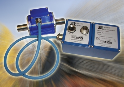
    Sevcon in Gateshead, which designs and manufactures high-quality motor controllers and system components for hybrid and electric vehicles, has driven efficiency into its equipment testing regimes by standardizing TorqSense transducers from Sensor Technology of Banbury.

    The stakes are high in the race to develop electric and hybrid vehicle technologies, with the winners likely to become leading suppliers to a global market worth literally billions. Sevcon develops drives for electric vehicles such as fork lift trucks, aircraft tow vehicles, golf buggies and scooters. When, in late 2011, it won funding to develop an electric motor controller for trucks, few people saw a high volume future for electric vehicles.
    Now, six years later, the whole market is very different. It's truly global and there seems to be no limit to the kind of vehicles that can be 'electrified'. Sevcon's latest GEN5 on-road electric motor controller is the result of a collaborative High Torque Density Switched Reluctance Drive System R&D project, with commercial and academic partners.
    IMAGE: Driving efficiency into electric vehicle R&D with wireless torque sensor
    Sevcon's Howard Slater says: "In 2011 we focused on bus and truck applications. We've since found that many different vehicles need similar levels of power. That's a huge market that didn't exist when we started. Last year we added 25 new jobs in R&D alone and engineering staff numbers have doubled in less than three years.
    As well as developing this cutting-edge technology and winning business in a hyper competitive market, Sevcon has to ensure its internal management systems are reliable, efficient and flexible. One of the ways it has done this is by standardizing Sensor Technology's TorqSense as the core component in its controller test rigs.
    In essence, a Sevcon controller is designed to vary the power or torque produced by an electric vehicle's drive motor. In tests a controller is paired with a motor and run for an extensive period, from one hour to 26 weeks, to check the complete speed and performance range over time.
    TorqSense is a wireless sensor, which is not physically connected to the test motor's shaft by slip rings. Instead, it monitors the torque via radio waves.
    A shaft twists very slightly when it rotates, the amount of deformation being proportional to the torque. TorqSense measures the deformation so that it can calculate torque. To do this two tiny piezoelectric combs are glued to the surface of the shaft at right angles to one another; shaft deformation will expand one comb and compress the other. A radio frequency signal emitted by the TorqSense is reflected back by the combs, with its frequency changed in proportion to the combs' deformation.
    "The procedure to set up the TorqSense is very simple and takes only moments," says Mark Ingham of Sensor Technology. "Solutions using other technologies would probably take several hours to set up.
    "TorqSense has an enormous overload capacity, which enables it to cope with robust and demanding test cycles, while its digital output signal can be fed straight into a computer program for instant analysis."
    The many advantages of TorqSense have led Sevcon to standardise it for all its test rigs throughout the company.
    Howard again: "We use TorqSense on four continents. We have a number of test rigs, each dedicated to a particular task. While it would be easy to swap a TorqSense from one rig to another, we in fact don't do that but follow a minimum disturbance routine so that we don't upset rig alignments and can thus quickly and efficiently carry out multi-test regimes.
    All of our test staff, from technicians to technical directors, right around the world, are fully trained on TorqSense. This means they can replicate each other's tests and if a person visits another site they instantly understand the local tests and experiments.

    More about TorqSense here: http://www.saelig.com/category/MFR00070.htm

    Thursday, September 14, 2017

    Lowered price! SSA3032X Spectrum Analyzer is now $2595!

    The price of the Siglent SSA3032X Spectrum Analyzer - previously $3295 - is now $2595! And the latest firmware upgrade gives free 1 Hz RBW selection! Most competing analyzers only offer 10 Hz!

    This represents a major saving for this model.

    In addition, on both the SSA30221X AND the SSA3032X the Tracking Generator Option (TG) will now be included at no charge.
    Please note: The free TG option is part of a temporary promotion. 

    But that is not all….. 


     1 Hz and 3 Hz* Resolution Bandwidth (RBW) positions are now added to both models. The lowest value before was 10 Hz.  Probably no other spectrum analyzer in this price range can do this. Not even close!

    https://www.saelig.com/product/ssa3032x.htm

    Wednesday, September 13, 2017

    What is "RBW" in a Spectrum Analyzer Specs?

    National Instruments has a nice answer (http://www.ni.com/white-paper/3983/en/)

    1. Resolution Bandwidth

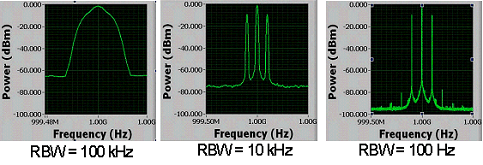
    The resolution bandwidth (RBW) determines the fast Fourier transform (FFT) bin size, or the smallest frequency that can be resolved.
    The following graphs represent the same signal with varying RBW.


    Figure 1. The Same Signal With Different RBW.
    The smaller RBW, on the right, has much finer resolution which allows the sidebands to be visible. Finer resolution requires a longer acquisition time. When acquisition time is a factor and the display needs to be updated rapidly or when the modulation bandwidth is wide, a larger RBW can be used. RBW and acquisition time are inversely proportional.  

    Tuesday, September 12, 2017

    Introducing the RIGOL DS2000E Series Digital Oscilloscope


    Uncompromised Debug Solution starting at just $647

    If your debug challenge requires advanced analysis capabilities
    and instrument performance on an extremely tight budget the DS2000E
    allows you to make no compromises

    • 1GSa/sec on all channels provides full 5X oversampling all the time 
    • Free Serial Decode/Trigger supports most of today's common standards
    • 28M Record Length on all channels enables long captures to find elusive problems
    • Vibrant 8 Inch Intensity Graded Display provides easy observation and analysis
    • Waveform Record/Capture, Advanced Math, and 17 trigger types 

    Greater performance than the Tek TBS2000 at less then half the price.


    Rigol DS2102E 100MHz 2-Ch Digital Oscilloscope

    Monday, September 11, 2017

    RTSA7550 Real-Time 27GHz Spectrum Analyzers See Intermittent and Frequency-hopped Signals.

    The compact RTSA7550 Real-Time Spectrum Analyzer is a powerful, full-featured spectrum analyzer designed to analyze wireless signals in real-time (not progressively scanned). This is essential for seeing intermittent and frequency-varying signals.


    The Model RTSA7550 has all the standard features of a conventional spectrum analyzer such as frequency controls, marker functions, and multi-trace functionality. Instead of scanning through a frequency range, the RTSA sees all frequencies at once, thus catching intermittent signals or transmissions that vary dynamically in amplitude or frequency-hopping. The PC-controlled RTSA7550 includes:  9kHz to 8, 18 or 27GHz frequency range; real-time spectrum graphing; real-time spectrogram viewing; real-time power spectral density display (persistence); real-time triggering; real-time time domain display; and real-time recording and playback. Real-time triggering allows for measuring complex data signals such as Wi-Fi and LTE. Sophisticated FPGA-based digital signal processing within the RTSA7550 enables the capture of elusive time-varying signals across an instantaneous bandwidth of up to 160MHz.
    The RTSA7550 has all the standard features of a sophisticated, expensive bench-top spectrum analyzer, but at far lower cost since it uses the display and processing power of an attached PC.  

    Read on here:  http://www.saelig.com/pr/rtsa7550.html


    Friday, September 8, 2017

    Vehicle Exhaust, Outdoor Environment, Fire Retardant and Work Center Testing Applications For Specialized RF Shielded Enclosures


    Flexible, portable, high attenuation EM RF shielded environments are in demand for many testing applications. Vehicles of all sizes, can be tested in a RFI / EMI screen rooms with proper intake and exhaust systems. Mobile outdoor RF isolation testing tents can be assembled on-site when needed in isolated areas. Fire retardant liners and systems support local fire code requirements. Work center structures assist semi-conductor manufacturing.


    Vehicle Enclosures
    Vehicles from small garden tractors to large aerospace units (Mil-STD 461) can be set up for testing in a modular unit with collapsible sections, removable thresholds and/or custom-sized doors. Select Fabricators has developed a new, removable threshold that eases entry into their patented single door, double magnet system (US Pat. No. 9,029,714) including level grade guides and recommended floor protection mats. The door itself is optionally removable as well as sized for the vehicle. A recent example of this design is a 20’ x 18’ vehicle door to accommodate the object under test.


    Thursday, September 7, 2017

    Using Current Probes

    When using current probes you should be aware of some common characteristics shared by current probes. All have some type of shielding to minimize the pickup of electrostatic fields radiating from the test conductor. Optimizing the design of the shield for maximum rejection has some compromises in other probe parameters. Thus, different vendors’ probes have differing ability to reject fast dv/dt signals in the test conductor. While the Teledyne LeCroy current probes have among the lowest voltage sensitivity in the industry you should still be aware of it. This means that wherever possible you should probe the circuit under test on the low voltage side of the circuit. When that is not possible a simple test can be used to quantify the electric field pick up in the actual circuit. Connect a short piece of wire to the test conductor. Do not terminate the opposite end. Place the jaw opening around the conductor and view the waveform. Because no current is flowing through the unterminated wire, any signal displayed in the waveform is due to the dv/dt coupling into the probe. Ideally, none of the voltage signal would be visible in the displayed waveform.

    Continue here:   http://snip.ly/ss2uh


    Wednesday, September 6, 2017

    Ramsey STP1100 Flexible RF Shielded Pouch Shields Phones

    The STP1100 (http://www.saelig.com/MFR00066/stp1100.htm) is specifically designed to rapidly collect and secure wireless devices at the scene by law enforcement personnel. Cellular phones and other wireless devices have quickly become one of the most important and valuable sources of investigative data. But that data has the high risk of being overwritten, deleted, locked-out, or corrupted unless the device is immediately RF shielded from the carrier's network, or even powered down. If a phone is "receiving service" it is vulnerable to remote access, remote data dumps, and remote lockdowns. If the phone is powered off, it is also vulnerable to auto lockdowns and authentication code changes for re-access.
    The small size and low cost of the STP1100 puts rapid and secure collection of wireless devices in the hands of every officer in the field for transport to their lab for further investigation. An evidence tag window and tags assure proper ID and chain of custody. Check out the STE3000F for a hands-on shielded environment to release and investigate the device. Replacement evidence tags are available (Part STPET1).


    Tuesday, September 5, 2017

    Saelig Introduces All-In-One MDO-2000E Oscilloscope Series

    All-In-One MDO-2000E Oscilloscope Series With Multiple Built-In Instruments
    Compact models have a built-in true spectrum analyzer, dual channel 25MHz AWG, DMM, and a power supply to suit educational and restricted space situations


    Fairport, NY, USA:  Saelig Company, Inc. has introduced the GW Instek MDO-2000E Series Oscilloscopes which combine several test instruments in one enclosure. An actual spectrum analyzer is included in the design, not just an FFT calculation to display the frequency domain. The series includes two instrument combinations: MDO-2000EG and MDO-2000EX. MDO-2000EG models have a built-in true spectrum analyzer and a dual channel 25MHz arbitrary waveform generator, while the MDO-2000EX models feature a built-in a true spectrum analyzer, an arbitrary waveform generator, a 5,000 count DMM, and a 5V/1A power supply. The first of its kind, MDO-2000EX is the only oscilloscope to provide a space-saving combination of spectrum analyzer, DMM and power supply, making it ideal for educational or space-restricted use.  The MDO-2000E Series is available in three bandwidths:  70, 100 and 200MHz and in 2 or 4 channel models.

    A conventional digital oscilloscope uses FFT calculations over the entire signal bandwidth up to half the sampling rate. But inadequate calculation capability means it is impossible to have a signal's detailed frequency information due to the insufficient frequency resolution from the calculation. In contrast, the MDO-2000E series analyzes just a defined signal spectrum of interest to allow engineers to effectively conduct precision signal measurements in the frequency domain. Users can input specific data of interest regarding the signal: center frequency, span, and start/stop frequency, similar to a traditional spectrum analyzer. While observing frequency domain display, engineers can observe waveform characteristics which are not easily seen from time domain waveforms, such as the harmonic composition of a waveform and the frequency characteristics of a modulation signal. Compared with an oscilloscope's FFT, the MDO-2000E series allows engineers to effectively conduct signal measurements both in the time and frequency domains.

    Offering an advantage over conventional spectrum analyzers, the spectrum function of MDO-2000E series can test signals that are below 9kHz, such as audio and vibration signals. The MDO-2000E series can also test signals that have a DC component without damaging the instrument. The MDO-2000E series offers the same capabilities as real-time spectrum analyzers, but faster than frequency sweeping. This is because the MDO-2000E series utilizes advanced digital circuitry and software to render the frequency display. Ordinary spectrum analyzers process narrow frequency bandwidths which are frequency swept over time. Thousands of frequency sweeps are collected to form a spectrum. The FFT settings of ordinary digital oscilloscopes are dependent on the horizontal scale or sample rate setting, which is totally different from the frequency range setting of the MDO-2000E series. Most DSOs will have insufficient frequency resolution.  

    Made by the Taiwanese test and measurement specialists GWInstek, the MDO-2000E oscilloscope series are available now from Saelig Company Inc.  For detailed specifications, free technical assistance, or additional information, please contact Saelig (585) 385-1750, via email: info@saelig.com, or by visiting www.saelig.com


    # # #